DUCT
SPACERS
APPLICATION:
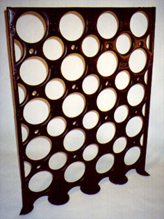
Duct spacers are designed to
temporarily support an array of ducts within a trench until it
can be filled with grout or similar suitable fill material. They
also maintain accurate duct separation and alignment, which promotes
reduced pulling tension. The spacer provides for independent support
and separation of each duct. Ample openings for concrete flow
is part of the spacer�s modular design. Optional foot pads assure
specified vertical separation between the trench floor and the
bottom of the first duct tier. Duct spacers produced by Formex,
in combination with vertical reinforcing rods and metal collars,
provide an effective means for splaying from duct bank to vault
or manhole. Vertical spreads to get over obstructions can also
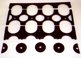
easily be accomplished in this manner. With Formex interlocking
module duct spacers, sweeps and bends are assembled much faster
and easier, and when locked into position, they stay put.
CONSTRUCTION:
Duct spacers produced by Formex
are unaffected by extremes of temperature, and virtually unbreakable,
due in part to the material used to produce them. Formex begins
with two sheets of high density polyethylene (HDPE) and makes
spacers to customer�s specifications by a molding process which
makes possible a rugged double wall construction with an exclusive
interlocking design, eliminating the need for banding. duct tier.
Job studies have proven use of this spacer results in lower overall
costs.
Click here for specifications
for Formex Interlocking Module Spacers
Click here to submit an information
request
|
DUCT
|
A
|
CH
|
CV
|
E
|
F
|
|
SIZE
|
2-WAY
|
3-WAY
|
4-WAY
|
|
2"
|
8
|
11 3/8
|
14 3/4
|
3 7/16
|
3 7/16
|
4 1/4
|
1 3/4
|
|
3"
|
10 1/4
|
14 3/4
|
19 3/8
|
4 9/16
|
4 9/16
|
4 3/4
|
2 1/4
|
|
4"
|
12 1/4
|
17 3/4
|
24 1/4
|
5 9/16
|
5 9/16
|
5 1/4
|
2 3/4
|
|
|
|
1 1/2" SEPARATION
|
|
DUCT
|
A
|
CH
|
CV
|
E
|
F
|
|
SIZE
|
2-WAY
|
3-WAY
|
4-WAY
|
|
2"
|
9 1/2
|
13 1/2
|
17 3/8
|
3 15/16
|
3 15/16
|
4 1/4
|
1 3/4
|
|
3"
|
11 1/4
|
16 1/4
|
21 3/8
|
5 1/16
|
5 1/16
|
4 3/4
|
2 1/4
|
|
4"
|
13 3/4
|
19 3/4
|
25 7/8
|
6 1/16
|
6 1/16
|
5 1/4
|
3 1/8
|
|
5"
|
15 7/8
|
22 7/8
|
30
|
7 1/16
|
7 1/16
|
5 7/8
|
3 5/8
|
|
6"
|
18
|
26 1/4
|
34 3/8
|
8 3/16
|
8 3/16
|
6 3/8
|
4 1/4
|
|
|
|
2" SEPARATION
|
|
DUCT
|
A
|
CH
|
CV
|
E
|
F
|
|
SIZE
|
2-WAY
|
3-WAY
|
4-WAY
|
|
2"
|
10 1/4
|
14 3/4
|
19 3/8
|
4 9/16
|
4 9/16
|
4 1/4
|
1 3/4
|
|
3"
|
12 1/4
|
17 3/4
|
24 1/4
|
5 9/16
|
5 9/16
|
4 3/4
|
2 1/4
|
|
4"
|
14 1/4
|
20 7/8
|
27 1/4
|
6 9/16
|
6 9/16
|
5 1/4
|
3 1/8
|
|
5"
|
16 3/8
|
24 1/8
|
31 3/4
|
7 5/8
|
7 5/8
|
5 7/8
|
3 5/8
|
|
6"
|
19 1/2
|
27
|
35 5/8
|
8 5/8
|
8 5/8
|
6 3/8
|
4 1/4
|
|
|
|
3" SEPARATION
|
|
DUCT
|
A
|
CH
|
CV
|
E
|
F
|
|
SIZE
|
2-WAY
|
3-WAY
|
4-WAY
|
|
2"
|
11 5/8
|
16 7/8
|
22 1/8
|
5 1/4
|
5 1/4
|
4 1/4
|
1 3/4
|
|
3"
|
14 1/4
|
20 7/8
|
27 1/4
|
6 9/16
|
6 9/16
|
4 3/4
|
2 5/8
|
|
4"
|
16 3/8
|
24 1/8
|
31 3/4
|
7 5/8
|
7 5/8
|
5 7/8
|
3 5/8
|
|
5"
|
19 1/2
|
27
|
35 5/8
|
8 5/8
|
8 5/8
|
6 3/8
|
4 1/4
|
|
6"
|
19 1/2
|
29 1/8
|
38 3/4
|
9 5/8
|
9 5/8
|
6 3/8
|
4 1/4
|
|
|
|
1" SEPARATION
/ BELL TELEPHONE
|
|
DUCT
|
A
|
CH
|
CV
|
E
|
F
|
|
SIZE
|
2-WAY
|
3-WAY
|
4-WAY
|
|
4"
|
11 11/16
|
17 1/8
|
22 3/8
|
5 5/16
|
5 5/16
|
3 2/3
|
2 5/8
|
| ** Standard
base clearance from trench floor is 1 1/2", 3" is
also available |
| A |
TYPE
OF SPACER |
M - Module
(Interlocking) |
U
- Unit Type Spacer |
| MB - Module
Base (Interlocking) |
IU
- Interlocking Unit Spacer |
| IC - Interlocking
Converter Module |
MC
- Module Cap (Interlocking) |
|
| B |
Indicates
the nominal duct size spacer is to accommodate.
Note: For converter module spacers, both duct sizes will be
shown. (i.e. 5-4) |
|
| C |
TYPE
OF DUCT |
A - Plastic duct; Iron pipe size
T - Bell spec AT 8546, Plastic duct
|
| |
| D |
Indicates
number of ducts abreast for each tier. |
| |
| E |
Horizontal
duct separation in 1/10". Note: For interlocking caps,
only horizontal dimension is shown. |
| |
| F |
Vertical
duct separation in 1/10". |
| A |
B |
C |
D |
E |
F |
TYPE OF
SPACER |
NOMINAL
DUCT SIZE |
TYPE OFDUCT |
DUCTS PER
TIER |
HORIZONTAL SEPARATION |
VERTICAL
SEPARATION |
| M |
5 |
A |
3 |
20 |
20 |
Click here to submit an information
request